

Commercial Flood Lights: Specification Guide
Oct 25, 2026
On many commercial sites the flood lighting layout looks adequate on paper yet produces uneven pools of light once installed. Dark zones appear between fixtures, glare reaches adjacent windows or walkways, and several units fail within the first wet season because water tracks along cables or collects at the lens gasket. These outcomes usually trace back to incomplete review of optics relative to mounting height, seal paths and finish durability rather than simple product shortage.
Correcting the issues after installation means extra lifts, re-aiming time and possible circuit changes. Specifiers who lock down material choices, ingress protection details, beam characteristics, power levels, mounting hardware and control method early reduce those risks and keep the lighting package aligned with the rest of the building services.
Material and Finish
Housing material determines long-term resistance to impact, UV and thermal cycling. Die-cast aluminum remains the common choice for flood lights because it balances weight, heat dissipation and structural rigidity. Wall thickness should be sufficient to accept threaded entries and mounting bosses without cracking under torque. Internal components need clear thermal paths so LED boards and drivers stay within rated temperatures.Housing material determines long-term resistance to impact, UV and thermal cycling. A current example of this build is the TL-TGD-JA1603, a 50 W anti-glare flood light in die-cast aluminum rated IP66.
Finish systems protect the aluminum. A multi-stage pre-treatment followed by polyester powder coating provides the baseline barrier. Coating thickness and adhesion must be verified so chips do not expose bare metal. Hardware, brackets and fasteners are typically stainless steel to avoid galvanic corrosion at contact points. Lens material is tempered glass for impact resistance and optical stability; plastic lenses may yellow or craze under prolonged UV and heat. Gaskets are silicone or equivalent compounds rated for continuous outdoor exposure and compression set resistance. When the specification lists these elements, the supplier can confirm compliance on the datasheet and sample.
- Confirm housing alloy and minimum wall thickness
- Require documented powder-coat process and thickness range
- Specify stainless fasteners and bracket material
- State tempered glass lens and gasket compound
IP Rating and Where Water Enters
Ingress protection must match the exposure. Most commercial flood lights carry an IP65 or IP66 rating, indicating dust-tight construction and resistance to water jets. Higher ratings such as IP67 appear when temporary immersion is possible. The rating alone is not enough; the paths where water can enter must be examined.
Cable entry glands are primary risk points. They must be correctly sized for the cable outer diameter, tightened to the stated torque and fitted with sealing washers. Rear or side conduit entries need compatible adapters and thread sealant. The lens-to-housing joint relies on a continuous gasket compressed by screws or a clamp ring; uneven torque or missing screws creates gaps. Drain holes, if present, must face downward and remain clear. Driver compartments should be isolated or potted so that any moisture that reaches the terminal block cannot bridge live parts. On site, installers must maintain the seal integrity during aiming and cable termination. Specifiers should require the IP test report that shows the exact test conditions used for the supplied configuration.
- Match IP rating to expected water exposure
- Detail gland size, type and sealing method
- Require even gasket compression and screw torque notes
- Isolate or protect the driver compartment
Beam Angle and Spacing
Beam angle controls how light is distributed across the target surface. Narrow beams (10-30 degrees) deliver intensity over distance for accent or long-throw tasks. Medium beams (40-60 degrees) suit general area coverage. Wide beams (90 degrees and above) fill broad surfaces from shorter setbacks. The selection must be checked against mounting height and the required uniformity ratio.
Spacing is derived from the beam and height. A common starting point places fixtures so that the beam edges overlap sufficiently to keep minimum illuminance above the design threshold. Too wide a spacing creates scalloped dark bands; too tight wastes energy and can raise glare. IES files allow calculation in lighting software to confirm average levels, uniformity and spill light. Aiming angle also matters: tilt beyond the designed range can push the beam onto unwanted surfaces or reduce effective coverage. When multiple beam options exist in the same family, the specification should list the exact distribution required for each location type. The TL-TGD-L3601 pairs a 36 W single-row array with a square extruded housing for a compact rectangular beam.
- Select beam angle from target size and setback
- Calculate spacing for uniformity using photometric data
- Limit tilt range to maintain intended distribution
- Request IES files for each beam variant
Wattage Against Mounting Height
Lumen output and wattage must rise with mounting height to maintain design illuminance. At low heights a modest wattage with wide optics may suffice. At greater heights the inverse-square effect demands higher lumen packages or tighter beams to keep light on the task area. Efficacy (lumens per watt) influences total connected load and heat management.
Driver current setting and LED binning affect delivered lumens over time. The specification should state initial lumen target at the chosen wattage, ambient temperature rating and any required lumen-maintenance projection. Over-specifying wattage increases glare and energy use; under-specifying leaves the surface below target after dirt depreciation and lumen drop. Coordination with the electrical layout ensures circuit loading and voltage drop remain acceptable when all fixtures operate at full output. Dimming capability allows later adjustment if field measurements show excess light. Within one housing family, the TL-TGD-H7201 sits at 72 W while sibling models step from 9 W to 168 W, keeping the optics consistent as the lumen package changes.
- Scale lumen package to mounting height and target lux
- State efficacy and ambient temperature limits
- Include lumen maintenance expectations
- Verify electrical loading at full output
Mounting Detail
Mounting hardware transfers wind load, self-weight and any vibration into the structure. Common options include adjustable yoke brackets for surface or pole mounting, slip-fitters for tenon tops, and wall plates. The bracket must allow the full aiming range required by the photometric layout while locking securely once set. Stainless or coated steel construction resists corrosion at pivot points.
Fixings into concrete, steel or masonry need appropriate anchors sized for the fixture weight plus wind force. Vibration-prone locations may require locking washers or thread-locking compound. Cable management should keep the supply cord from chafing against sharp edges during aiming. Access for future maintenance, such as driver replacement or lens cleaning, must remain possible without full fixture removal. The specification drawing should dimension the mounting interface, bolt pattern and maximum projected area so the supplier can confirm bracket compatibility. The TL-22ATG6403-200W carries a 200 W dual-row array on an aimable head for high-mounted aiming adjustments.
- Define bracket type and adjustment range
- Size anchors for weight and wind load
- Provide locking method after aiming
- Ensure maintenance access clearances
Control
Control method determines energy use, scene flexibility and integration with building systems. Simple photocell or time-switch operation suits basic dusk-to-dawn needs. 0-10 V or DALI dimming enables daylight response and scheduled reduction. Wireless nodes or networked controllers support grouping, remote override and status reporting. Surge protection at the fixture or branch level guards the driver against line transients.
The driver must match the chosen protocol and dimming curve. Wiring topology (daisy-chain, star, bus) affects cable length and voltage drop on control lines. When fixtures sit on multiple switched circuits, consistent standby behavior prevents unexpected dark patches. Specifiers should list the required interface, dimming range, and any sensor or gateway compatibility so the supplier can supply matching gear trays or external modules. Coordination with the controls contractor early avoids protocol mismatches at commissioning.
- Select protocol to match building system
- Confirm driver dimming range and curve
- Detail control wiring topology and lengths
- Include surge protection requirements
Salt Mist Resistance
Salt mist exposure accelerates corrosion on metal housings, brackets and fasteners. Resistance depends on base material, pre-treatment, coating integrity and galvanic compatibility. Aluminum housings with proper powder coat thickness and sealed edges perform adequately when the coating remains unbroken. Stainless steel fasteners and brackets reduce rust staining and seizure at joints. Gasket and gland materials must not degrade when salt deposits form and are later washed by rain. Drainage paths prevent prolonged standing of saline water in recesses. The finish system should be continuous across machined faces and mounting interfaces. Specifiers can request salt-mist test data that records hours of exposure and evaluation criteria for blistering, creep and adhesion. On-site maintenance such as periodic fresh-water rinsing further extends service life. These measures keep structural and electrical integrity intact without relying on unproven coatings or untested assemblies. Documentation is prepared per project when the exposure level is identified on the drawings.
Submittal Files
Complete submittal packages allow review before release for fabrication. Standard files include the product datasheet with dimensions, electrical data and material notes, the IES photometric file for each optic, the IP test report for the supplied configuration, LM-80 data for the LED package, and the certificate of conformity. All documents are issued per project on request so that the exact variant, finish and accessories appear on the paperwork. Submit the package alongside drawings and quantities for cross-check against the specification clauses.
Matching Products: Wall Washer Light / Spot Lights / Bollard Lights / Underwater Lights / Wall Lights / Flood Lights / Outdoor Strip Lights / Inground Lights / Step Lights
Submit project drawings and quantities so the lighting package can be checked against mounting heights, aiming requirements and control intent. The supplier will return a coordinated proposal with the required submittal files. Contact Us
You Might Also Like
-

TL-DMD-G3602 In-ground Light 72 W IP67 Polarized
-

TL-TGD-H0901 Slim Square Flood Light 9 W IP66 Extruded Al...
-

TL-TGD-H16801 Slim Square Flood Light 168 W IP66 Extruded...
-
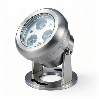
HYD-4077 Surface Mounted Underwater Light 3 W IP68
-
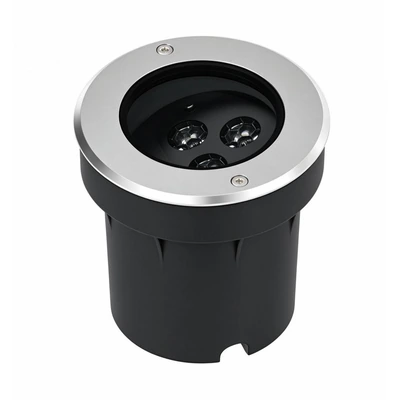
TL-DMD-G03F4 In-ground Light 9 W / 12 W IP67 RGBW
-

TL-TGD-I0603 Round Flood Light 18 W IP66 Aluminum