

Commercial Outdoor Wall Lights Specification Guide
Oct 22, 2026
During the final commissioning walk-through of a commercial building exterior, two failure modes frequently appear on the vertical facade. The first is optical: wall luminaires mounted over textured cladding create harsh hot spots directly above and below the housing, leaving dark valleys between fixture positions and blinding pedestrians with unshielded glare at entryways. The second is mechanical: within weeks of energization, internal condensation forms on the inside of the glass lenses, followed shortly by driver failures and corroded mounting screws staining the facade masonry.
Both issues originate during the specification phase rather than the installation phase. When a luminaire schedule lists only wattage, color temperature, and a generic enclosure rating, it leaves critical structural and optical variables undefined. Preventing premature field failures and achieving uniform facade luminance requires writing tight, defensive specifications that govern housing metallurgy, secondary moisture barriers, beam geometry, thermal limits, and back-box integration before the equipment is ordered from the supplier.
Material Selection and Surface Finish
The housing of an exterior wall luminaire serves as both its structural anchor and its primary heat sink. The base material must dissipate thermal energy from the LED array while resisting oxidation caused by atmospheric pollutants, acid rain, and ultraviolet radiation. Specifiers generally select between three primary metals: die-cast aluminum, extruded aluminum, and stainless steel.
For die-cast components, the copper content within the aluminum alloy dictates its structural longevity. Standard die-cast alloys often contain higher levels of copper to improve castability, which accelerates galvanic corrosion when exposed to moisture. For commercial applications, specify low-copper aluminum alloys - such as EN AC-44300 or equivalent grades containing less than 0.1 percent copper. Extruded aluminum housings, typically formed from 6063-T5 or 6061-T6 alloys, offer lower porosity and higher thermal conductivity than cast parts, yielding a smoother substrate for surface coatings.
Where fixtures are mounted at pedestrian level or in environments with chemical wash-downs, stainless steel housings are appropriate. However, standard 304-grade stainless steel will exhibit tea-staining and surface pitting in chloride-rich air. When raw metallic finishes are required, 316L marine-grade stainless steel with a passivated or electropolished surface reduces microscopic crevices where corrosive agents accumulate.
For painted aluminum housings, the pretreatment and coating process is as important as the base alloy. A durable finish specification should require:
- Multi-stage chemical pretreatment, utilizing chromate-free conversion layers or zirconium-based washes to etch the aluminum and create a molecular bond.
- An epoxy primer coat applied over the pretreated substrate to seal surface pores and provide edge coverage on sharp cast corners.
- A UV-stabilized architectural polyester powder topcoat, cured to a dry film thickness between 60 and 80 microns, preventing chalking and pigment fading under direct sun exposure.
- 316-grade stainless steel external fasteners isolated from the aluminum body via nylon or EPDM washers to prevent bimetallic corrosion that seizes screws during maintenance.
- Tempered soda-lime or borosilicate glass lenses, minimum 4mm to 5mm thick, flush-mounted to the bezel so water cannot pool on horizontal ledges.
- Impact resistance rated to at least IK07 for upper facade positions, stepping up to IK09 or IK10 for public walkways, loading docks, and low-level perimeters.
IP Rating and Moisture Ingress Paths
Specifying an IP65 or IP66 rating on a luminaire schedule does not prevent water damage on site unless the design accounts for thermal pressure differentials and wall-surface runoff. An IP65 rating verifies defense against low-pressure water jets, while IP66 covers heavy seas and powerful jets. Neither rating tests what happens when a hot luminaire is suddenly doused by cold rain.
During operation, the internal air volume of a sealed wall light heats up and expands. When a rainstorm strikes the exterior housing, the rapid drop in surface temperature causes the internal air to contract, creating a partial vacuum inside the fixture. This vacuum actively sucks moisture past conventional gaskets and through the microscopic capillaries between stranded copper wires inside the supply cable. Once inside, the water condenses on the cold inner face of the glass lens and pools around the driver terminals.
To prevent vacuum-induced failures and wall-cavity leakage, the specification must address five distinct ingress vectors:
- Gasket composition and compression: Avoid closed-cell neoprene or foam gaskets that take a permanent compression set after thermal cycling. Specify molded, continuous-loop silicone gaskets with a Shore A hardness between 40 and 60, seated in a machined tongue-and-groove channel that limits compression to 25-30 percent of the gasket thickness.
- Lens bonding: For narrow-profile up-down wall lights, mechanical clips often apply uneven pressure across the glass. Specify lenses that are either retained by a full-perimeter cast bezel with torqued fasteners or bonded directly to the housing using structural, UV-resistant neutral-cure silicone adhesive.
- Pressure equalization vents: Require an integrated breather membrane - typically made of expanded polytetrafluoroethylene (ePTFE) - built into the housing body. This hydrophobic membrane allows air molecules to pass through freely, equalizing internal pressure during thermal cycling while blocking liquid water droplets and salt crystals.
- Internal potting and chamber separation: Specify dual-chamber luminaires where the optical cavity is sealed separately from the wiring and driver compartment. If an electrician fails to torque the access cover properly on site, the LED board and optics remain sealed against the elements. Drivers should feature potted electronics to protect components from humidity during installation.
- Rear cable entry sealing: Most water enters wall lights from behind, running down the facade or migrating through the conduit system. Specify fixtures with a recessed rear entry gland (IP68 rated) or an internal terminal block equipped with an integrated water-stop grommet. Never rely on field-applied silicone sealant around the backplate perimeter as the primary moisture barrier, as this traps water behind the fixture and forces it into the junction box.
Beam Angle, Optics, and Spacing Ratios
Selecting the wrong optical distribution on a vertical surface turns architectural features into visual hazards. Because wall lights sit directly adjacent to the surface they illuminate, the light strikes the wall at an extreme grazing angle. Even minor miscalculations in beam spread or mounting offset will exaggerate mortar joint irregularities or leave dark scalloped zones across the building envelope.
Optical control in exterior wall luminaires relies on Total Internal Reflection (TIR) PMMA or polycarbonate lenses, hydroformed anodized aluminum reflectors, and glare accessories such as honeycomb louvers or snoots. Specifiers must match these optical tools to the desired lighting effect:
- Narrow grazing beams (8 to 15 degrees): Used on high vertical columns, pilasters, or textured stone facades to create long throws of light with dramatic shadow play. The optical center of the fixture must sit close to the wall. Note that narrow beams highlight every surface flaw; if the masonry or plaster contractor has uneven tolerances, a narrow beam will expose them.
- Medium accent beams (20 to 40 degrees): The standard choice for up-down architectural rhythm on multi-story facades, framing window mullions, and illuminating mid-height walls. These optics balance vertical throw length with lateral beam spread.
- Wide flood and asymmetric distributions (60 to 110+ degrees): Designed for perimeter walkways, entry canopies, and security perimeters where the goal is horizontal ground illumination rather than vertical wall painting. Forward-throw asymmetric optics push light away from the building base, illuminating a 3-meter to 5-meter pathway without wasting lumens on the wall itself.
For narrow accent work on pilasters and stone reveals the 20 W accent body GAS125MF holds the beam tight without washing the whole bay, while rhythmic up-down patterns call for a twin-aperture body such as GAS2416A (2 x 10 W) that splits output between the upper and lower apertures.
To achieve continuous horizontal uniformity along a pathway or facade base using wide-beam or asymmetric wall lights, the spacing-to-mounting-height ratio is critical. For standard asymmetric forward-throw wall packs mounted at 3 meters above finished grade, a spacing distance of 2.5 to 3.5 times the mounting height (7.5 to 10.5 meters center-to-center) maintains an acceptable minimum-to-average uniformity ratio on the ground plane, typically targeting 0.25 to 0.40 for commercial walkways.
When specifying up-down decorative cylinders for visual rhythm rather than continuous uniformity, spacing is dictated by structural grid lines (such as window bays or column centers). In these layouts, specify independent optical control for the upper and lower apertures. For example, a luminaire mounted 2.5 meters off the ground on a 10-meter tall wall requires a wide 60-degree downlight beam to wash the immediate entry threshold cleanly, paired with a tight 15-degree uplight beam to reach the upper cornice without spilling into adjacent windows.
Glare control must be built into the specification whenever fixtures are mounted below 3 meters or adjacent to glass curtain walls. Require recessed light sources with a physical cut-off angle of at least 30 degrees, supplemented by internal matte-black anti-glare baffles or replaceable hex-cell louvers on any uplight aperture that pedestrians might look down into from upper-level balconies or stairs.
Wattage Against Mounting Height and Thermal Balance
Over-specifying wattage is a common cause of visual discomfort and premature component degradation in exterior wall lighting. Unlike pole-mounted floodlights that lose intensity over long throw distances, wall-mounted luminaires are positioned inches away from the target surface and close to the pedestrian line of sight. High lumen packages in compact wall housings create intense surface luminance directly adjacent to the fixture, ruining night vision adaptation and violating dark-sky ordinances.
Furthermore, wall luminaires operate in a restricted thermal environment. Pole lights benefit from convective wind flow around all sides, whereas a wall light is bolted flat against a building facade that often absorbs solar heat all afternoon and radiates it back into the fixture at dusk. Because the surface area of an architectural wall sconce is limited by aesthetic constraints, driving the LEDs at high currents inside a compact housing will elevate the junction temperature beyond safe thresholds, accelerating lumen depreciation and shifting color coordinates.
Use the following mounting height and wattage benchmarks when building a commercial specification:
- Low-level mounting (0.5 to 1.8 meters): Typical for knee-walls, ramps, patio perimeters, and immediate doorway identification. Specify 2W to 6W (delivering roughly 150 to 500 luminaire lumens). Optics should be heavily shielded or frosted, utilizing downward-only distributions to prevent eye-level glare.
- Pedestrian scale and single-story facades (2.0 to 3.5 meters): Standard height for commercial entryways, colonnades, and retail frontages. Specify 8W to 18W (delivering 700 to 1,800 luminaire lumens). For up-down fixtures, split this wattage between the two arrays (for example, 2x8W).
- Mid-rise commercial facades (4.0 to 6.0 meters): Used for logistical perimeters, loading zones, and second-story architectural accents. Specify 20W to 35W (delivering 2,200 to 3,800 luminaire lumens) with medium-to-narrow optics or forward-throw roadway distributions.
- High facade positions (6.0 to 10.0+ meters): Reserved for high-level security perimeters or tall architectural column grazing. Specify 40W to 60W (delivering 4,500 to 6,800 luminaire lumens). At this power level, verify that the fixture body incorporates external cooling fins arranged vertically so dust does not settle and block airflow.
Where a facade sits above that band, the 72 W waist-drum cylinder wall light TL-TSD-G2403 carries the output up without a longer bracket.
Regardless of wattage, specify the correlated color temperature (CCT) and color rendering index (CRI) alongside strict binning tolerances. For stone, brick, wood, and warm architectural plasters, 2700K or 3000K with a minimum CRI of 80 (or 90 for hospitality facades) brings out material depth. For glass, steel, and concrete facades, 4000K provides a crisp visual contrast. Require 3-step MacAdam ellipse (3 SDCM) color consistency across the batch. Without a 3-step specification, slight variations in phosphor thickness will turn a white plaster wall into a patchwork of greenish and pinkish beams when ten up-down lights are installed in a continuous row.
Mounting Details and Structural Integration
A wall luminaire specification frequently fails during installation because the fixture backplate does not align with the site electrical rough-in, or the cladding material cannot support the cantilevered weight of the housing. Contractors on commercial sites encounter brick masonry, precast concrete, metal insulated panels, Exterior Insulation and Finish Systems (EIFS), and glass curtain wall mullions - each requiring a different mechanical interface.
The biggest point of friction on site is the transition from the building conduit to the luminaire wiring chamber. Many architectural wall sconces have slim profiles that cannot sit flush over a standard surface-mounted junction box, while recessed junction boxes are often set too deep behind exterior stone veneer.
To eliminate field improvisations that void IP ratings, incorporate these mounting details into the specification:
- Two-piece mounting architecture: Specify fixtures that utilize a separate heavy-gauge mounting sub-plate or universal adapter plate. The electrician anchors this plate to the wall, pulls the building wires through a central gasketed port, and makes the electrical terminations onto an integrated terminal block while the heavy luminaire body hangs safely on a temporary steel retention tether. Once wired, the luminaire body slides over the sub-plate and locks via recessed stainless steel grub screws.
- Stand-off and spacer kits: When facades feature rough-hewn stone, split-face block, or vertical architectural fins, a flat backplate will rock unevenly and crush the rear gasket on one side while leaving a gap on the other. Specify supplier-supplied spacer brackets or stand-off collars that hold the fixture body 15mm to 30mm off the uneven stone while routing the supply cable through a sealed central stem.
- EIFS and insulated facade coordination: Never allow heavy cast luminaires to be anchored directly into synthetic stucco or rigid foam insulation. Require the supplier to provide mounting templates early in the construction schedule so the general contractor can install structural plywood backer blocks or extended threaded rod anchors tied back to the primary structural sheathing before the facade wrap is sealed.
- Conduit entry flexibility: For industrial walls or retrofit projects where conduits run across the exterior surface, standard rear-entry architectural sconces cannot be used without awkward stand-off boxes. Specify luminaire housings that feature cast-in, threaded side or top conduit entries (M20 or 1/2-inch NPT) sealed with flush hex plugs when not in use.
- Vibration resistance: For wall lights mounted on parking garage spandrels, bridge abutments, or railway concourses, specify internal components and mounting brackets tested for vibration stability to prevent work-hardening and fracturing of the mounting ears.
Where the facade allows no stand-off at all, the 5 W recessed body 50238 sits flush in solid masonry and moves the sealing plane behind the finish surface.
Control Protocols and Electrical Architecture
Commercial energy codes and dark-sky regulations increasingly prohibit running exterior facade lighting at full output from dusk until dawn. Specifying the control interface for outdoor wall lights requires matching the luminaire driver architecture to the building management system while accounting for long cable runs, voltage drop, and lightning-induced surges.
For simple perimeter and security applications, integral photocells or astronomical timeclocks at the distribution panel provide basic on-off switching. However, architectural facades and multi-use commercial plazas typically require dimming and zoning capabilities. The two dominant wired protocols are 0-10V and DALI-2.
When specifying 0-10V dimming for exterior wall runs, be aware of voltage drop across the low-voltage control wires over long facade perimeters. This voltage drop causes the fixtures at the far end of the daisy-chain to dim to a lower level than the fixtures near the panel, creating visible brightness gradients across the building face. For commercial projects with more than 15 fixtures on a circuit or runs exceeding 50 meters, specify DALI-2 (Digital Addressable Lighting Interface) drivers. DALI-2 transmits digital commands immune to analog voltage drop problems, allows individual addressing of up-down apertures without pulling separate switch legs, and provides bi-directional feedback on driver status and lamp failure.
Regardless of the control protocol, the electrical specification must include robust protection against grid transients and environmental interference:
- Surge Protection Devices (SPD): Exterior wall wiring runs along the outer skin of the building, making it susceptible to inductive spikes from nearby lightning strikes and heavy HVAC switching loads. Specify an internal or driver-integrated surge protection rating of at least 4kV to 6kV (line-to-line and line-to-earth) as standard, increasing to a dedicated 10kV inline SPD module for exposed perimeters and elevated facade positions.
- Inrush current management: LED drivers draw a high momentary inrush current when energized simultaneously. Request the peak inrush current amplitude (Ipeak) and duration (Twidth) from the supplier during the design phase so the electrical engineer can size Type C circuit breakers properly and prevent nuisance tripping at dusk.
- Remote vs. integral drivers: Compact architectural wall lights (such as narrow slot lights or mini-cylinders) often cannot fit an AC-DC driver internally. If specifying low-voltage (24V DC or constant current) wall fixtures with remote drivers, mandate the maximum allowable cable distance and wire gauge between the remote driver enclosure and the fixture head to prevent line loss.
- Emergency egress compliance: Where exterior wall luminaires sit above fire exit doors, they must function as emergency life-safety lighting. Because internal battery packs rarely survive sub-zero winter temperatures inside small exterior housings, specify these wall positions to run off a central inverter system, or select cold-weather rated fixtures (-20 degrees Celsius minimum) with insulated, self-testing NiMH or LiFePO4 battery chambers.
Salt Mist Resistance
When a commercial project is located near a coastline, marine estuary, or heavy industrial zone, airborne chlorides and sulfur compounds will destroy standard exterior powder coatings within a few seasons. Salt mist settles on the warm luminaire body, and as moisture evaporates, recrystallization occurs inside microscopic pores in the paint film. This mechanical expansion blisters the coating from the metal underneath, leading to filiform corrosion and structural failure of the lens retaining ring.
For projects in high-salinity environments, the specification must upgrade both the material science and the coating system. Require marine-grade low-copper aluminum alloys (containing less than 0.1 percent copper) or solid 316L stainless steel bodies. Where aluminum is used, specify a multi-layer marine coating process: chemical conversion pretreatment, a zinc-rich or high-build epoxy primer, and a super-durable polyester or fluoropolymer topcoat totaling at least 80 to 100 microns in thickness. All external hardware, mounting plates, and cable glands must be 316 stainless steel or nickel-plated brass with anti-seize compound applied to threads during assembly. Validation of this finish system via neutral salt spray testing (such as ISO 9227 or ASTM B117) must be verified prior to order placement.
Submittal Files
To prevent unapproved substitutions during procurement and ensure the installed luminaires match the engineering calculations, require a formal documentation package from the supplier before granting submittal approval. The specification should mandate the following five core documents, which are issued per project on request:
- Comprehensive product datasheet detailing alloy grade, coating thickness, input wattage, delivered lumens, CRI, CCT tolerance, operating temperature range, and physical dimensions.
- Verified photometric IES file (or LDT equivalent) generated from goniophotometer testing of the specific optic and wattage combination, allowing accurate point-by-point verification in lighting design software.
- IP test report confirming the ingress protection rating of the luminaire enclosure.
- LM-80 data for the LED package alongside TM-21 lumen maintenance projections, verifying thermal longevity at the specified drive current.
- Certificate of conformity demonstrating compliance with applicable regional electrical safety and electromagnetic compatibility standards.
Matching Products: Wall Lights / Wall Washer Light / Step Lights / Bollard Lights / Spot Lights / Flood Lights
Preparing a commercial exterior lighting schedule or resolving complex facade mounting details? Send our engineering team your architectural drawings, lighting layouts, and target quantities for a technical review and project quotation. Contact Us to request submittal packages and photometric files tailored to your project requirements.
You Might Also Like
-

WAJTS-176-F18 High Power LED Flood Light 72 W DC 24 V IP65
-

GAS2404A-500 Bollard Light 5 W IP65 Die-Cast Aluminum
-
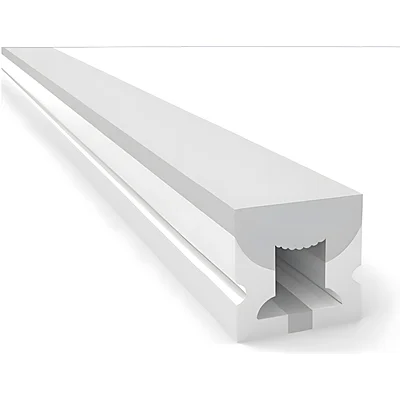
10x10 mm Three Sides Emitting LED Neon Flex GM-A2835Y-120...
-

LB-DT860408 Surface Mounted Downward Wall Light 8 W IP66 ...
-
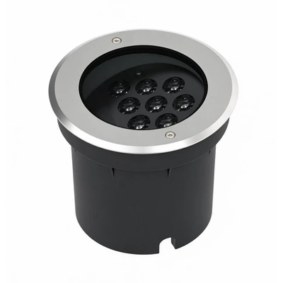
TL-DMD-G06F4 In-ground Light 18 W / 24 W IP67 RGBW
-
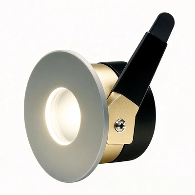
BE-STL0111 Step Light 1 W IP67 Aluminium