

Specifying Commercial Outdoor Strip Lights And Neon Flex
Nov 03, 2026
On a reflected ceiling plan or a landscape elevation, a continuous line of light reads as a clean, unbroken graphic stroke. The drawing indicates a twenty-meter run of linear lighting tucked into an exterior limestone soffit or wrapping the radius of a poured concrete planter. Six months after handover, the site reality often diverges from that intent. The run shows a noticeable drop in brightness from the feed end to the termination, the warm white output has shifted toward green or amber above individual diodes where moisture has wicked past a site-made end cap, or the silicone jacket has buckled out of its mounting track because thermal expansion was not accommodated in the containment detail.
These failures rarely originate in the diode chip itself. They occur because flexible linear lighting is a semi-finished system whose final optical, thermal, and environmental performance depends on how the tape, encapsulation, aluminum channel, power topology, and site terminations are specified together. Writing a robust specification for outdoor strip lights and flexible neon requires defining each of these layers so the electrical contractor is not left making waterproofing or voltage-drop calculations on a scaffold.
Emitter Architecture, Dot Pitch, and Close-View Optics
The primary optical decision on any exterior linear detail is whether the fixture is viewed directly as a luminous line or used indirectly to graze an adjacent material. This distinction dictates the choice between surface-mounted diode (SMD) arrays and chip-on-board (COB) phosphor constructions, alongside the required diode density per meter.
Discrete SMD packages mount individual LED chips along the flexible printed circuit board (FPCB) at fixed intervals. Common densities range from 60 to 240 LEDs per meter. When an SMD strip is installed inside a shallow aluminum extrusion with an opal polycarbonate or silicone diffuser, the physical distance between the emitting surface and the diffuser lens, known as the mixing chamber depth, must exceed the pitch distance between adjacent diodes to achieve a dot-free appearance. If a contractor installs a 60-LED-per-meter strip (roughly 16.6 millimeters pitch) into a shallow 8-millimeter architectural recess for a step nosing, individual bright spots will remain visible both on the lens and as scalloped reflections on polished stone or wet paving.
COB linear strips address this close-view scalloping by mounting bare flip-chips directly onto the FPCB at very tight intervals, often 380 to over 500 chips per meter, and covering the entire row with a continuous bead of phosphor-doped silicone. The result is an unbroken emitting surface with a wide 180-degree beam angle before any secondary optics are applied. For shallow handrail slots, stair nosings, and facade reveals where the viewer stands within two meters of the light source, COB architecture or high-density SMD (minimum 160 LEDs per meter) paired with a deep-section optical jacket is necessary to maintain a continuous visual line.
- Direct-view architectural outlines and shallow cove details require either COB continuous-phosphor construction or SMD densities where diode pitch is narrower than the depth of the diffusing cavity.
- Indirect grazing of rough-textured masonry or board-formed concrete benefits from discrete SMD emitters paired with co-extruded linear lenses (such as 15-degree or 30-degree profiles) that collect the Lambertian output and project it down the wall plane.
- Color consistency across long facade runs requires specifying a maximum tolerance of 3-step MacAdam ellipse (3 SDCM) across all reels delivered to the project, backed by single-bin procurement from the supplier.
- For hospitality terraces, retail portals, and textured stone facades, a minimum Color Rendering Index (CRI) of Ra 80 is standard for circulation, while Ra 90 with an R9 value above 50 is specified where warm timber, brickwork, or skin tones are illuminated.
The dotless COB Single Color LED Strip (320 to 528 LEDs/m, IP20 to IP68) holds that unbroken line on a step nosing viewed from close range.
Encapsulation Systems, Water Ingress Paths, and Cut-Point Integrity
An ingress protection rating is never a permanent characteristic of a product family; it is a conditional boundary that depends on the encapsulation method, the orientation of the mounting channel, and the integrity of every cut point and cable entry. Specifiers must look beyond a headline rating and define the material chemistry and sealing mechanics required by the exact installation position.
Three primary jacketing methods are used for exterior linear runs: heat-shrink tubing, open-channel resin potting, and solid silicone co-extrusion. Heat-shrink sleeves offer basic mechanical protection against dust and stray splashes inside sheltered soffits, but the thin wall thickness and lack of internal bonding leave an air cavity around the circuit board. As the strip heats up during operation and cools down after switching off, the internal air expands and contracts. This pressure differential creates a peristaltic pumping effect that draws humid exterior air and condensation through microscopic gaps around the wire entry.
Potted strips place the FPCB inside a U-shaped silicone shell or aluminum profile and fill the cavity with liquid polyurethane or silicone resin. Polyurethane cures to a rigid, durable finish with strong resistance to mechanical abrasion, making it suitable for deck edges, though standard aliphatic polyurethanes can amber slightly under sustained ultraviolet exposure unless UV-stabilized grades are specified. Silicone co-extrusion, used in flexible architectural neon, passes the LED assembly and multiple grades of optical and structural silicone through a cross-head extrusion die simultaneously. This creates a monolithic, vulcanized solid body with no internal air voids, preventing internal condensation and offering stability against ultraviolet radiation and thermal cycling from minus 40 to plus 60 degrees Celsius.
- Sheltered downward-facing soffits and deep overhang coves require protection against wind-driven dust and insects, alongside sealed cable tails to prevent moisture wicking into the copper traces.
- Exposed vertical facade grooves, handrail slots, and planter perimeters subject to direct rain and hose-down cleaning require solid encapsulation where the jacket bonds directly to the lead wire insulation and the end cap.
- Upward-facing channels in plazas, steps, or flat coping stones act as water collection troughs; if drainage slots are not detailed into the architectural sub-channel, the strip sits in standing water and must be specified with molded injection end caps rather than field-glued caps.
- When a linear run transitions into a fountain basin, reflective pool, or cascade edge, standard exterior silicone neon is insufficient; submerged runs require a dedicated underwater construction with an IP68 continuous immersion rating and a stated depth, utilizing anti-wicking water-block cables and terminations sealed at the supplier with zero field-made joints allowed inside the wet zone.
The jacketed 2835 Single Color LED Strip (60 to 280 LEDs/m, IP20 to IP68) covers soffit and facade reveals where the viewer stays further back.
Electrical Topology, Voltage Drop, and Driver Architecture
Every flexible LED strip is built on a thin rolled or electrodeposited copper circuit board. Because the cross-sectional area of those copper traces is constrained by the width and thickness of the flexible substrate, the traces exhibit measurable electrical resistance. As current flows down the strip from the power feed, voltage drops progressively along the length of the run in accordance with Ohm's law. When the local voltage at the far end of the strip falls below the forward voltage threshold required by the series-parallel LED groups, lumen output visibly decays from the feed end to the tail end.
Selecting 24 V DC rather than 12 V DC halves the current required to deliver the same wattage per meter, cutting the resistive voltage drop in half and doubling the achievable single-feed run length. For short step details or sign boxes under five meters, standard constant-voltage 24 V DC strips utilizing simple current-limiting resistors on each cut segment are adequate, provided the copper weight of the FPCB is at least two to three ounces per square foot. On longer architectural reveals, between 10 and 20 meters, specifiers should require constant-current integrated circuit (CC-IC) strips. These designs replace passive resistors with miniature linear current-regulator chips on each segment. As voltage drops along the copper busbar from 24 V down to 19 V, the onboard IC dynamically adjusts to maintain constant current through the diodes, delivering uniform luminance from the first meter to the last.
Where a project demands runs up to 30 meters from a single feed location without intermediate power injection boxes, 48 V DC constant-current architectures reduce line current further. Regardless of strip topology, the wiring scheme must account for the feeder cable gauge between the remote driver enclosure and the start of the strip. Feeding a medium-length 24 V DC run from both ends (dual-end feed) or via a parallel T-junction at the midpoint reduces the effective electrical path length by half without requiring a change in strip voltage.
- Specify 24 V DC as the baseline operating voltage for general exterior detailing, reserving 48 V DC for continuous facade lines where access for intermediate junction boxes is restricted by cladding panels.
- Mandate two-ounce or three-ounce copper FPCB substrates in the technical specification to minimize trace resistance and prevent localized heating at the initial power entry pads.
- For dimmable exterior zones, match the driver dimming method to the control hardware: pulse-width modulation (PWM) constant-voltage drivers must operate at a switching frequency high enough (typically above 1,500 Hz) to avoid visible flicker on architectural security cameras and mobile phone sensors.
- Calculate driver loading with a minimum 20 percent headroom margin above the total connected strip wattage to account for cold-start inrush current and high ambient temperatures inside exterior IP-rated driver enclosures.
Bending Geometry and Section Profiles for Curved Details
Flexible linear lighting is only flexible along one plane unless specifically engineered otherwise. Attempting to bend an encapsulated strip or neon profile against its internal circuit board axis during installation fractures the solder joints of the surface-mount components and delaminates the copper tracks from the polyimide carrier. The specification drawings must distinguish between flat-bend (vertical bend) and side-bend (horizontal bend) orientations based on how the luminaire meets the architectural curve.
Front-emitting (front-bend) profiles orient the FPCB horizontally, parallel to the light-emitting face. These sections bend up and down like a roller coaster track, making them correct for wrapping over convex or concave drum walls, arched window heads, and undulating ceiling coffers. Side-emitting (side-bend) profiles orient the FPCB vertically inside the silicone extrusion, perpendicular to the luminous face; the light exits through a side optical chamber. This allows the neon to bend left and right across a flat plane, following curved planter walls, sweeping stair stringers, and organic pathway borders.
Every profile cross-section has a minimum bend radius dictated by its width, height, and internal copper construction, commonly between 60 millimeters and 300 millimeters depending on the section size. Forcing a 16-by-16-millimeter side-bend neon around a tight 30-millimeter architectural corner will pinch the silicone jacket and crush the internal FPCB. Where sharp 90-degree corners are required, the contractor must use a molded L-connector or make a cut and join with a short flexible jumper cable rather than bending the body of the strip.
- Verify the bending plane on every curved detail: specify front-bend sections for arches and curved soffits, and side-bend sections for sinuous plan-view contours on walls or ground planes.
- State the minimum permissible bend radius on the detail drawings and prohibit bending across the non-flexible axis or within 30 millimeters of an encapsulated end cap or solder joint.
- For complex three-dimensional curves that twist simultaneously in two planes, such as spiral column wraps or sculptural trellis structures, specify either a 360-degree round emitting section with a specialized spiral-flex core or a dual-axis free-bend extrusion.
- Where wide viewing angles are needed on exposed corners or fins, three-sided emitting neon sections offer 270-degree visibility while still mounting into a standard flat rear aluminum channel.
A flat 10x10 mm Side Emitting LED Neon Flex follows that plan-view curve and still seats into a standard rear channel.
Thermal Management, Mounting Profiles, and Mechanical Retention
Encapsulating an LED strip inside solid silicone protects it from water, but silicone is a poor thermal conductor compared to aluminum. As the electrical power density increases, heat generated at the semiconductor junction must pass through the solder pads, the FPCB, the silicone wall, and into the surrounding air or mounting substrate. If that heat remains trapped, the elevated junction temperature accelerates lumen depreciation (shortening the L70 lifetime), shifts the chromaticity coordinates of the phosphor, and degrades the mechanical elasticity of the jacket.
Low-output orientation and accent runs operating at 4 to 8 watts per meter can generally dissipate their thermal load through natural convection when mounted in open-air clips or shallow u-channels. Medium- to high-output linear runs, between 12 and 20 watts per meter, used for grazing facade columns or lighting deep coves require continuous contact with an anodized aluminum extrusion that acts as a heat sink. Embedding a high-wattage silicone neon tightly inside a routed timber groove, expanded polystyrene insulation, or unventilated concrete chase without an aluminum liner traps heat and leads to premature yellowing or diode drop-out.
Mechanical retention also requires attention to thermal expansion. Silicone has a significantly higher coefficient of thermal expansion than aluminum or masonry. Over a 10-meter facade run exposed to direct daytime sun followed by cool night air, a silicone neon extrusion will expand and contract by several millimeters relative to its rigid aluminum track. If both ends are pinned tight against adjacent wall returns or if the contractor applies continuous structural adhesive along the back of the silicone, the strip will snake sideways or pop out of the channel jaw during peak afternoon temperatures.
- Balance wattage per meter against the thermal mass of the mounting detail: limit deeply recessed, unventilated non-metallic slots to low-wattage accent outputs under 10 watts per meter.
- Use continuous marine-grade anodized aluminum mounting profiles with serrated internal silicone-grip ribs for overhead soffit installations; never rely on self-adhesive backing tape alone for exterior or inverted mounting, as moisture and thermal cycling cause acrylic adhesives to peel away from silicone and masonry.
- Detail a 5- to 10-millimeter expansion gap at the non-feed end of long aluminum tracks and between butt-jointed neon runs to absorb longitudinal thermal growth without buckling.
- For grazing installations where the luminaire is visible from below, specify flanged or deep-recessed aluminum profiles fitted with asymmetric louvers or snap-in glare shields to conceal the bright emitting face from pedestrian sightlines.
On a wrap where the line has to stay visible from the sides, a 13 mm Round 270-Degree LED Neon Flex covers the curve without a change of section.
Field Cutting, Terminations, and Cable Entry Detailing
The majority of water ingress failures on exterior linear installations happen at the ends of the run, not through the middle of the extruded body. Every LED circuit board is divided into discrete series-parallel groups separated by printed cut marks (solder pads). Cutting a strip anywhere other than the designated cut mark breaks the electrical circuit for that entire segment, leaving a dark dead zone of 25 to 100 millimeters at the end of the run.
In an exterior specification, the transition from the cut mark to the feeder cable and the sealing of the terminal end cap must be explicitly defined. Molded injection terminations bond liquid silicone directly to the jacket and cable jacket under heat and pressure, creating a unified seal. Whenever facade dimensions can be verified prior to fabrication, ordering bespoke cut-to-length runs with molded cable tails and end caps eliminates the most common site failure point.
When architectural tolerances require field cutting on site, such as fitting into curved stonework built on site, the specification must dictate the termination hardware. Standard slip-on silicone end caps filled with neutral-cure adhesive rely entirely on the installer cleaning the jacket, applying primer, filling the cap void without trapped air, and allowing a 24-hour cure before moving or energizing the strip. Mechanical compression-seal (screw-lock) connectors and dual-wall adhesive-lined heat-shrink assemblies with internal hot-melt potting collars provide a more repeatable mechanical seal for contractors working on outdoor scaffolding, provided the connector system matches the exact cross-sectional dimensions of the extrusion.
- Coordinate the unit cut-increment length (for example, 50 millimeters on a 24 V strip or 8.3 millimeters on a free-cut constant-current design) with the architectural joinery details so dark tail zones are avoided at corners.
- Specify bottom-entry or side-entry cable exits rather than straight end-entry tails whenever two runs must butt together end-to-end; end-entry cable boots add 15 to 30 millimeters of non-illuminated dead space between sections, creating a visible dark gap in the line of light.
- Mandate the use of internal anti-wicking ferrules or gel-filled waterproof splice enclosures inside the dry junction box; water can travel down the inside of a multi-strand copper power cable via capillary action if the outer cable sheath is nicked or terminated inside a damp conduit.
- Require continuity and insulation testing of all field-sealed strips prior to snapping them into high-level facade channels where post-installation access requires mobile elevating work platforms.
Control Protocols for Single-Color, Tunable, and Addressable Runs
Integrating outdoor strip lights into a commercial building management system or architectural lighting control network requires aligning the strip's internal channel count with the appropriate protocol decoder and power supply layout. Simple single-color runs can be dimmed directly via phase-cut, 0-10 V, or DALI-2 dimmable drivers, where the driver modulates its DC output directly. On complex facades, splitting the driver and the control decoder often simplifies maintenance: a non-dimmable constant-voltage industrial power supply feeds a multi-channel DALI-2 or DMX512 constant-voltage decoder mounted in a weatherproof local enclosure.
Tunable white (two-channel warm and cool white) and RGBW (four-channel color-changing plus dedicated white) strips share a common positive anode wire and use individual negative cathode return wires for each color channel. For RGBW facade grazing, specifying an integrated emitter package (where the red, green, blue, and white dies sit inside a single SMD housing) rather than alternating separate RGB and white packages prevents color striations and chromatic shadows on close-offset surfaces.
Addressable (pixel-controlled) neon and strip lights introduce digital data lines alongside the power bus, allowing individual segments of 50 to 166 millimeters to be controlled independently for dynamic media facades or chasing perimeter animations. Serial protocols (such as SPI) are sensitive to electromagnetic interference and signal degradation over long feeder cables, typically limiting the distance between the pixel controller and the first diode to under 10 meters without differential signal repeaters. Parallel protocols (such as native DMX512 addressable strips with dual redundant data lines) allow longer starter cable runs and ensure that if a single pixel IC fails in the middle of a facade run, the bypass data line continues passing the signal to the remaining downstream segments rather than freezing the rest of the line.
- Specify dual-signal redundant DMX512 protocol rather than single-wire SPI for exterior addressable facade installations to prevent a single damaged pixel from blacking out the remainder of the run.
- Ensure RGBW specifications explicitly call for 4-in-1 integrated SMD packages plus optical mixing chambers so individual color dots do not separate on reflective wet surfaces.
- Size multi-core control and power cables between the remote driver vault and the fixture entry to account for both the combined maximum current on the common anode wire and the shielding requirements of the digital data pair.
Salt Mist Resistance
Exterior linear lighting installed near marine environments, coastal boardwalks, or cold-climate roadways treated with de-icing salts faces aggressive chloride corrosion that attacks both the encapsulation boundaries and the mounting hardware. While solid silicone extrusions are chemically inert to salt spray, the vulnerable points in a coastal installation are the metallic mounting tracks, the copper circuit board edges near field cuts, and the brass or nickel-plated pins inside snap-on connectors. Standard untreated aluminum profiles quickly develop white oxide pitting, which expands and pinches the silicone jacket or causes retaining clips to fracture. For corrosive environments, mounting channels must be specified in marine-grade anodized aluminum (minimum 15 to 20 microns anodizing thickness) or 316 stainless steel clips. All terminations in salt-mist zones should be specified with silicone over-molding applied at the supplier rather than mechanical metallic gland connectors, isolating every copper conductor and solder pad from airborne saline moisture.
Submittal Files
To verify compliance before procurement and installation, the electrical contractor and lighting specifier should require a complete technical submittal package from the supplier. Standard documentation issued per project on request includes the comprehensive product datasheet detailing mechanical dimensions, bend direction, minimum bend radius, and watts per meter; photometric LM-79 files (IES or LDT format) reflecting the actual encapsulated optical output rather than bare-board values; LM-80 lumen maintenance data for the LED package; third-party IP test reports corresponding to the specified encapsulation and termination method; project-specific cut-length schedules and schematic wiring diagrams showing driver placement and feeder cable gauges; and the formal certificate of conformity.
Matching Products: Wall Washer Lights / Spot Lights / Bollard Lights / Underwater Lights / Wall Lights / Flood Lights / Outdoor Strip Lights / Inground Lights / Step Lights
Preparing a linear facade, cove, or landscape lighting package? Send us your architectural elevations, run lengths, and control schedule so our engineering team can prepare a project-specific cut-length layout, voltage-drop calculation, and quotation. Contact Us to discuss your project requirements.
You Might Also Like
-

GAS1024-800 Bollard Light 5 W IP65 Die-Cast Aluminum
-
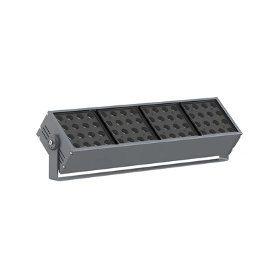
TL-TGD-JA6403 Anti-Glare Single-Row Aimable Flood Light 2...
-

13 mm Round 270-Degree LED Neon Flex GM-A2835Y-120-X-IPX ...
-
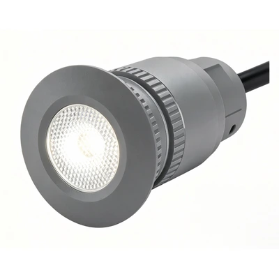
BE-STL0102 Micro Step Light 1 W IP67 Aluminium
-
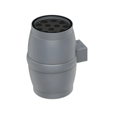
TL-TSD-G2403 Up-and-Down And Single-Direction Cylinder Wa...
-

TL-TGD-I1203 Round Flood Light 36 W IP66 Aluminum