

Exterior Step Lights: Commercial Specification Guide
Nov 03, 2026
On a newly handed-over commercial terrace, a wide stone stair often reads at night as a distracting row of bright hotspots along the side wall, while the center of each walking surface drops into shadow. Pedestrians approaching from the upper level see only the dark edges of the nosings, and those ascending look directly into unshielded emitters that ruin their night vision. When someone places a foot on the middle of a tread, the beam from a poorly positioned wall fixture is blocked by their own leg, throwing a hard shadow right over the next step edge where visual clarity is needed most.
The architectural reflected ceiling plan or landscape lighting layout rarely predicts this failure because two-dimensional drawings treat step lights as simple graphic symbols spaced at equal intervals. A plan view does not show the vertical interplay between riser height, tread depth, nosing overhang, and the grazing angle of the luminaire. Without calculating how the beam exits the housing in section view, a layout that looks neat and symmetrical on paper leaves the actual transitions between horizontal treads and vertical risers either washed out by glare or starved of measurable illuminance.
Mounting Position: Riser, Tread, Side Wall, and Stringer
Where the luminaire sits within the stair geometry dictates how light strikes the walking surface and how shadows form when the stair is in use. Specifiers generally choose between four primary mounting locations: recessed into the riser, recessed into the tread, set into an adjacent side wall, or surface-mounted onto a structural stringer.
- Recessed into the riser: Placing the fixture in the vertical face of the step throws light forward across the horizontal tread directly below it. Because the light originates behind the nosing of the upper step, the emitter remains hidden from someone viewing the stair from above. However, on a long flight seen from the bottom landing, the vertical face of every riser is in the direct line of sight. Riser-mounted fixtures therefore require strong downward beam redirection or physical shielding so they do not blind people walking up the stairs. When a pedestrian steps onto the tread, their foot lands in front of the light source, casting a shadow forward toward the nosing of the lower step, which means the fixture on that lower step must illuminate its own tread right back to its riser face.
- Recessed into the tread: Setting the fixture flush into the horizontal walking surface directs light upward onto the riser face and the underside of the nosing above it, or uses an internal reflector to push a grazing wash across the tread surface. Tread mounting defines the vertical plane of the step well, making the stair easy to read from the bottom. The trade-off is upward light spill. Anyone descending the stair looks straight down into the apertures unless the optics use deep internal louvers or side-emitting prism lenses. Furthermore, a foot placed near the edge of the step can cover the lens entirely, blocking illumination for a moment and subjecting the glass to direct shoe impact and grit abrasion.
- Set into a side wall or cheek wall: Mounting fixtures in the vertical walls flanking a staircase keeps the treads and risers free of penetrations and conduit runs. Light washes across the tread perpendicular to the direction of travel. This position avoids direct view of the light source from both the top and bottom of the stair, provided the aperture has a downward cut-off. The limitation is lateral throw. Because the light skims across the surface at a shallow angle, the area directly beneath the wall fixture receives intense illuminance while the far side of the stair receives very little. On stairs wider than 1.5 meters, a single side wall run leaves the opposite edge dark, requiring fixtures on both walls or an intermediate handrail system. Shadows cast by a pedestrian's legs fall sideways across the tread rather than forward or backward, which preserves visibility of the nosing directly ahead.
- Mounted on an open stringer: On steel or timber stairs with open risers and exposed structural stringers, recessed housings frequently lack the depth required for containment. Surface-mounted or shallow-recessed stringer fixtures attach directly to the inner face of the steel channel or flat bar. They behave optically like side wall fixtures but sit much closer to the tread surface, often just 30 to 50 millimeters above the walking plane. At this grazing height, even minor surface textures on concrete or anti-slip nosing strips cast long shadows across the step, so the optical window needs to sit as high on the stringer profile as structural tolerances allow.
Optical Distribution: Beam Angles, Throw, and Asymmetry
Step lighting operates at extreme grazing angles. A fixture mounted 100 millimeters above a tread must distribute light across a horizontal distance of 280 to 350 millimeters from riser to nosing, or up to 2,000 millimeters laterally from a side wall. Standard symmetrical cone distributions fail in this geometry because half the beam hits the tread two centimeters in front of the lens, creating an intense hot spot, while the upper half shoots out into open space as wasted spill light and glare.
Effective step illumination relies on asymmetric forward-throw optics. An internal reflector or total internal reflection (TIR) lens collects the upper portion of the LED output and bends it downward at an angle between 15 and 35 degrees below the horizontal plane. When checking photometric files, specifiers should look at the vertical candlepower distribution curve. Peak intensity must occur well below the 90-degree horizontal line, with near-zero output at 85 degrees and above, so that the beam reaches the far edge of the tread without crossing the eye level of someone standing on the lower landing.
Horizontal beam spread must match the mounting orientation. For a riser-mounted fixture centered on a 1.2-meter-wide flight, a wide horizontal spread of 90 to 110 degrees allows a single unit to cover the width of the tread without leaving dark triangles in the corners next to the stringers. Conversely, if a narrow 30-degree spot distribution is placed in a riser, it paints a narrow streak down the center of the step and leaves the outer edges unlit. When lighting from a side wall, a medium-wide horizontal beam combined with a flat vertical blade of light pushes illumination across the width of the stair while confining the beam between the riser and the nosing, preventing light from spilling over the front edge onto the step below and blurring the visual boundary between levels.
Two-way distributions, where a wall-mounted fixture emits light both downward and upward, require careful restriction on stairs. While an upward wash looks attractive on a flat landing wall or along a level pedestrian ramp, placing a two-way fixture on a sloped stair wall directs the upper beam straight into the eyes of people walking down the flight. Two-way output should be reserved for intermediate flat landings where pedestrians pause and turn, while the sloped flights themselves use only downward-directed optics.
Glare Control, Louvers, and Visual Comfort
A staircase forces pedestrians to view luminaires from below when ascending and from above when descending. At night, the human eye adapts to low ambient background levels on exterior walkways. If a step light presents an exposed, high-luminance LED source or a brightly lit diffuser flush with the wall, the sudden contrast causes disability glare, temporarily masking the physical edge of the step nosing just as the person needs to judge foot placement.
- Eyelid and hooded faceplates: A solid metal hood covering the upper half of the aperture physically blocks any upward light transmission. Because the upper shield protrudes slightly or sits flush over a recessed cavity, the emitter is hidden from view until the observer's eye drops below the cutoff angle, which generally cannot happen on a standard stair pitch.
- Angled blade louvers: Horizontal louvers set at a 30- to 45-degree downward pitch divide the aperture into small optical slots. They allow forward throw across the tread while blocking high-angle views into the lamp cavity. On exterior stairs subject to vandalism or heavy foot traffic, cast aluminum or stainless steel louver blades cast integrally with the faceplate resist bending and damage much better than thin stamped sheet inserts.
- Deep-recessed optical chambers: By pulling the LED board and lens 25 to 40 millimeters back from the front bezel and positioning the source inside the top lip of the housing, the body of the fixture acts as its own cutoff baffle. The visible window shows only a softly lit curved reflector backplate. This indirect internal bounce eliminates direct view of the diode and produces a smooth, low-luminance gradient across the tread, though it reduces total lumen efficiency compared to direct lens systems.
- Honeycomb baffles and prismatic glass: On tread-mounted uplights where a protruding hood would create a tripping hazard, a blackened aluminum honeycomb grid placed beneath a tempered glass lens cuts off side-angle glare. Frosted or micro-prismatic glass further diffuses the point source, preventing a sharp spot reflection if the glass becomes wet with rain.
Aperture Size, Recess Depth, and Construction Coordination
Integrating recessed step lights into cast concrete, masonry, or stone stairs requires coordination long before the electrical contractor arrives on site to pull wire. The physical housing, typically a plastic, composite, or cast aluminum rough-in backbox, must be fixed to the timber formwork before concrete is poured, or mortared into the blockwork core before stone cladding is laid.
Recess depth is the primary structural constraint. On a cast-in-place reinforced concrete stair, steel rebar cages usually sit 40 to 50 millimeters behind the finished concrete face to maintain structural cover against corrosion. If a specification calls for a recessed step light with a 110-millimeter-deep backbox on a riser face, the installer will hit the main structural steel bars. For risers and thin parapet cheek walls, shallow-recess housings with depths between 50 and 75 millimeters allow the backbox to sit entirely within the concrete cover zone or within the thickness of the mortar bed and stone cladding veneer, avoiding clashes with structural reinforcement.
When stairs are clad in natural granite, limestone, or porcelain tile over a concrete core, the cut-out dimensions and flange style determine the finish quality. Flanged fixtures feature an overlapping outer trim bezel of 5 to 12 millimeters that covers minor chipping along the saw-cut edge of the stone. Trimless (flangeless) fixtures sit flush with the finished stone face for a clean architectural plane, but they require CNC water-jet cutting of the stone riser or tread off-site, or a secondary plaster-in frame that is skimmed and painted on stucco walls. Specifiers must lock in the backbox dimensions during the shop drawing phase so the stone fabricator can cut the exact rectangular or circular openings before the treads and risers are delivered to the site.
Where the opening has to stay inside the thickness of the stone or the plaster, the BE-STL0102 micro step light (1 W, IP67, D16 or D20 cut-out at 35 mm recessed depth, 25 / 45 / 60 degree beam options) keeps the aperture within that envelope.
Conduit entry points into the backbox also need planning. Bottom and rear entries are easiest to conceal inside a concrete mass, whereas side entries allow easier daisy-chaining from step to step along a stringer wall without deep bends in the rigid conduit. The backbox must include an internal terminal block or enough cubic volume to house waterproof gel-filled wire connectors along with the incoming and outgoing supply cables.
Spacing Along a Flight and Riser Height Coordination
A common specification error is calling for step lights on a fixed horizontal spacing, for example, "install side wall step lights at 1,500 mm centers along all exterior stairs and ramps." While fixed linear spacing works well along a continuous flat ramp, applying it to a stepped flight creates chaotic illumination. Because stair treads follow a strict modular rhythm (typically 280 to 320 mm going with a 150 to 175 mm riser), a fixed linear spacing means the first fixture might sit directly over a nosing, the second fixture halfway back on a tread, and the third jammed tight into the internal corner of a riser where the step lip blocks half its beam.
Step lights on a flight must be indexed to the stair geometry itself, not to a tape-measure interval. For side wall installations, fixtures are commonly placed on every second or third tread, positioned at a consistent height above the tread line (typically 100 to 200 mm above the nosing line) and centered horizontally between the riser face and the front nosing. Mounting a fixture too low and too close to the front nosing causes the beam to spill over the edge onto the tread below, creating a double shadow line that confuses a pedestrian's depth perception.
When flights change total height between landings, such as an upper flight of twelve risers followed by a lower flight of seven risers, the spacing rhythm must adapt so that both the top and bottom steps of every flight receive dedicated illumination. Building codes and life-safety guidelines generally demand clear visual definition at the start and end of any level change. If an every-third-step spacing leaves the final bottom tread unlit on an odd-numbered flight, the spacing on that section must compress to every second step on the final transitions so the bottom nosing is never left in darkness.
For riser-mounted fixtures on wide monumental stairs (for instance, 3 to 6 meters wide), spacing is determined horizontally across each riser as well as vertically up the flight. Staggering fixtures on alternating risers often fails because it creates a visual checkerboard pattern that disrupts the clear horizontal line of the steps. Instead, aligning fixtures in continuous vertical columns up the stair, spaced 1.2 to 1.8 meters apart horizontally and corresponding to handrail divisions, reinforces the path of travel while lighting every tread along those active walking lanes.
Mechanical Load, Walk-Over Ratings, and Housing Materials
Staircases are high-impact circulation zones. Fixtures mounted near foot level are kicked by hard-soled shoes, struck by luggage carts and maintenance equipment, and exposed to thermal shock when cold rain hits a warm lens. Specifying residential-grade sheet metal or thin polycarbonate housings on a commercial project leads to cracked lenses and dented bezels within the first year of operation.
- Impact resistance (IK rating): For riser, side wall, and stringer locations, the faceplate and lens assembly should carry an impact rating of IK08 to IK10. Tempered soda-lime or borosilicate glass lenses of at least 4 to 8 millimeters thickness, supported by a continuous silicone perimeter gasket and a heavy die-cast aluminum or 316 stainless steel frame, absorb direct kicks and stone impacts from landscaping machinery without shattering.
- Static walk-over load: When a fixture is recessed directly into the horizontal tread surface or flat into a landing walkway, it must carry vertical static and dynamic loads. A pedestrian stepping directly onto a lens concentrates high point pressure, especially from narrow shoe heels, while maintenance carts impose rolling loads. Tread-mounted luminaires require a mechanical load rating of at least 500 kg to 2,000 kg (roughly 5 kN to 20 kN). To survive this load without cracking the masonry around it, the outer recessed sleeve must be embedded solidly into the structural concrete slab or mortar bed, transferring the downward force straight through the housing body to the base structure rather than hanging by a thin top bezel on brittle tile edges.
- Surface temperature limits: On public stairs, terraces, and hotel pool decks where people may sit on the steps or walk barefoot, the maximum external surface temperature of a tread-mounted lens or riser faceplate must remain comfortable to touch, typically staying below 40 to 45 degrees Celsius under normal ambient operating conditions. Low-wattage LED arrays paired with thick metal housings that conduct heat back into the masonry mass keep surface temperatures well within safe limits.
Ingress Protection and Water Entry Paths
An ingress protection rating is never a fixed, single number for the entire category of step lights. The required rating depends on where the fixture sits on the staircase, how water drains across the masonry, and whether the housing can become submerged during heavy rainfall.
Water attacks exterior step lights through four specific pathways: direct pressurized spray from facade cleaning hoses, capillary siphon action along the power cable jacket, thermal breathing through the lens gasket when rain cools a running fixture, and standing water pooling inside the recessed backbox. When an LED fixture operates for several hours, the air inside the sealed optical chamber warms and expands. If a sudden downpour washes cold rainwater over the step, the internal air cools rapidly and contracts, creating a vacuum that tries to suck moisture past the lens seal or straight through the microscopic gaps between copper wire strands inside the supply cable.
For side wall and stringer fixtures mounted well above the tread line where water sheets past vertically and drains away immediately, an IP65 rating protects against rain and low-pressure washdown jets. However, fixtures recessed into a step riser sit right at the junction where rainwater waterfalls from tread to tread, and debris or autumn leaves often pile against the faceplate, holding wet mud against the gasket for days. Riser fixtures therefore benefit from an IP66 or IP67 rating to withstand heavy water cascading down the stair and periodic high-pressure cleaning.
The BE-STL0111 (1 W, IP67, D40 cut-out at 40 mm recessed depth, asymmetric beam at 2700 K / 3000 K / 4000 K) is built for that riser position, delivering 120 lm from a single LED.
Tread-mounted fixtures recessed horizontally into the walking surface face the harshest conditions. Even on stairs built with a slight 1% to 2% forward pitch for drainage, water pools on top of the flat lens, and water that seeps through the mortar joints between stone slabs collects inside the recessed mounting sleeve below the fixture body. A tread-mounted fixture must carry an IP67 rating as a baseline, and IP68 if the recessed housing sits in a drainage channel or low landing pocket where the body remains underwater for prolonged periods. To prevent internal condensation from thermal vacuum, these housings require an integrated breathable membrane vent (such as a sintered PTFE vent plug) to equalize air pressure without admitting liquid water, paired with a pre-potted cable entry or an anti-wicking water-stop barrier inside the wiring compartment.
Wattage, Color Temperature, and Material Reflectance
Step lights do not need high lumen packages; they operate just centimeters away from the target surface, and excessive output creates blinding contrast against dark surroundings. Most commercial exterior applications require between 1W and 6W per fixture, delivering 30 to 250 delivered lumens at the aperture after optical and louver losses. A 2W louvered fixture on a riser easily meets commercial egress illuminance targets across a 300-millimeter tread depth while keeping surface luminance low.
The architectural finish of the staircase heavily alters both the required wattage and the perceived color temperature of the light. Dark flamed basalt, slate, or charcoal-tinted concrete absorbs up to 85% of incident light, whereas pale travertine, brushed limestone, or white painted steel reflects the majority of the beam. When lighting dark stone treads, specifiers often increase fixture output by one power tier or tighten the spacing to ensure the nosing remains clearly discernible against the dark surface. On light-colored polished stone, wattage should be kept low and optics diffused to avoid harsh specular reflections off the step surface.
Material color also shifts the apparent Correlated Color Temperature (CCT) of the beam. A 3000K warm white LED washing across honey-toned sandstone or terracotta brick picks up the warm pigments of the substrate, making the reflected light appear closer to 2400K or 2700K. That same 3000K fixture mounted on a galvanized steel industrial stair or a cool gray concrete car park ramp reads noticeably more neutral. Generally, 2700K and 3000K are specified for hospitality terraces, heritage stone steps, and timber-accented landscapes where visual warmth is desired, while 4000K is selected for office complexes, transit stairs, and concrete structures where crisp contrast with cold architectural materials is prioritized. Regardless of the nominal CCT chosen, specifying a tight MacAdam ellipse binning tolerance (3-step SDCM or tighter) is critical on a staircase, because ten to twenty fixtures sit right next to one another in a rhythmic sequence where any green or pink tint shift between units is immediately visible to the naked eye.
Driver Topology, Remote Access, and Dimming Controls
Choosing between an integral in-body driver (mains voltage 110V-240V AC input directly to the luminaire) and a remote driver (low-voltage 24V DC constant voltage or constant current input) depends on the physical size of the step light and the maintenance strategy of the site.
Integral AC drivers eliminate the need for external power enclosures and simplify voltage drop calculations over long cable runs, as standard mains wiring can loop from step to step down an entire flight. However, fitting an AC-DC power supply inside a compact housing increases the required recess depth and generates additional internal heat. Small-aperture architectural step lights, such as miniature 35 mm circular spots or ultra-slim linear riser slots, have no physical room for an integral mains driver and must run on remote low-voltage power.
The mains route is covered by the BE-STM0301 (3 W, 220-240 V AC with a built-in driver, IP55, 250 lm, 64 x 122 x 60 mm cut-out).
When specifying remote drivers for a staircase, three installation details require coordination on the electrical drawings:
- Accessible enclosure location: A remote driver cannot be buried inside concrete or sealed behind mortared stone risers. It must be housed in a weatherproof IP66 junction box or plant room cabinet located within a serviceable zone, such as underneath the stair soffit if there is an accessible under-croft, inside a nearby landscape bollard pedestal, or inside a recessed wall access panel on the landing.
- Voltage drop and cable gauge: On a long monumental stair running 24V DC fixtures in parallel, resistance along the copper wire reduces the voltage reaching the end of the line. If the cable cross-section is too small or the run exceeds recommended distances, the fixtures at the bottom of the stair will appear dimmer than those near the driver, or may fail to strike altogether. Dividing long flights into balanced multi-circuit home runs and sizing cable gauges for a maximum 3% to 5% voltage drop maintains uniform output from top to bottom.
- Series vs. parallel wiring: Constant-current LED modules require series wiring (daisy-chaining positive to negative in a closed loop), whereas 24V DC constant-voltage fixtures wire in parallel. Installers on site frequently damage constant-current LEDs by connecting them in parallel to a constant-voltage supply; clear wiring schematics on the submittal drawings prevent costly commissioning blowouts.
When stairs are integrated into a wider facade or landscape control system using DALI-2, 0-10V, or DMX protocols, dimming behavior at the bottom of the curve requires attention. During late-night curfew hours or on hospitality dining terraces, step lights are often dimmed down to 10% or 5% output to lower ambient brightness. Low-grade drivers exhibit noticeable visible flicker, step-changes, or drop-out dead zones below 15% load, or cause some fixtures on a flight to extinguish while others remain faintly lit. Specifying logarithmic dimming curves with smooth resolution down to 1% ensures that every step on the flight dims in unison without flicker or uneven dropouts.
On the low-voltage side the BE-STL0104 (1 W, 24 V DC, 1-10 V dimming, IP65, 150 lm, D55 cut-out at 50 mm recessed depth) carries that control range at the fixture.
Salt Mist Resistance
Staircases in coastal environments, waterfront boardwalks, and regions where de-icing road salts are spread on steps during winter face aggressive chloride corrosion. Standard polyester powder coatings over high-copper aluminum alloys quickly blister and peel when salt crystals lodge inside screw threads and behind mounting bezels, locking up fasteners so the fixture cannot be opened for service.
For high-salinity environments, specifiers have two reliable material routes. The first is a marine-grade 316 or 316L stainless steel faceplate and housing, passivated and electropolished to minimize surface pores where salt deposits can anchor. When stainless steel trim is paired with an aluminum recessed backbox or internal heatsink, nylon washers and insulating sleeves must isolate the two metals to prevent galvanic corrosion where they touch in the presence of salt water. The second route is a low-copper die-cast aluminum housing that undergoes multi-stage chromate or zirconium conversion pre-treatment, followed by an epoxy primer coat and a UV-stabilized polyester topcoat. All external hex screws, cable glands, and mounting springs must remain 316 stainless steel coated with anti-seize compound during installation.
Submittal Files
To support consultant review, lighting calculations, and site coordination, our team compiles a structured technical submittal package tailored to the project schedule. The documentation set includes the technical datasheet detailing electrical and mechanical parameters, photometric IES files for point-by-point illuminance modeling on the stair geometry, the IP test report verifying ingress protection, and LM-80 data covering lumen maintenance of the LED source. For contractor coordination, we provide a dimensioned cut-out and mounting detail drawing showing backbox depths and conduit entries, alongside the certificate of conformity. All test reports and submittal files are issued per project on request from us as your lighting supplier.
Matching Products: Step Lights / Inground Lights / Wall Lights / Bollard Lights / Wall Washer Lights / Spot Lights / Flood Lights / Outdoor Strip Lights / Underwater Lights
Preparing a stair lighting schedule or resolving a difficult recess detail on site? Send us your stair plans, riser and tread dimensions, and project quantities so our engineering team can prepare a complete specification package and pricing proposal. Contact Us
You Might Also Like
-
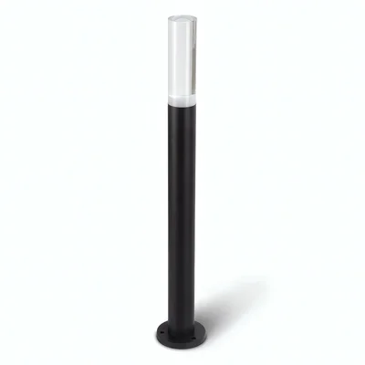
GAS1065-780 Bollard Light 3 W IP65 Die-Cast Aluminum
-
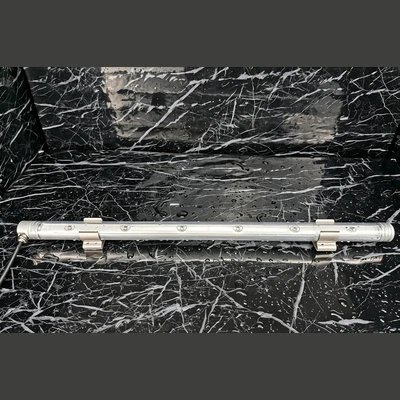
PUYSL-T8-1200 IP68 Underwater LED Linear Light 5 W
-

BL-BO20010-400 Bollard Light 10 W IP65 Die-Cast Aluminum
-

540103 LED Underwater Spot Pool Light 3 W 316 SS IP68
-

BE-SPL0102 Spot Light 1 W IP67 Aluminium
-

TL-TGD-K1803 Round Flood Light 54 W IP66 Die-Cast Aluminum