

Commercial Specification Guide For Exterior Wall Washers
Nov 03, 2026
When a commercial building facade is energized for the first time at night, a common defect is the appearance of harsh scallops along the base, a blinding hot spot one meter up the wall, or a bright horizontal band just below the parapet while the middle section remains dark. On the reflected ceiling plan or the elevation drawing, the luminaires were drawn as simple rectangles spaced evenly along the perimeter. The drawing assumed that light behaves like a uniform cone of paint, ignoring the inverse-square law and the sharp vertical incidence angles created when a fixture sits close to a tall vertical plane. Because the architectural drawings rarely show the photometric throw in section against the actual depth of the cornice or the reveal of the window mullions, the site installation reveals optical mismatches that were invisible on paper.
The physical cause of these visual defects almost always comes down to a collision between civil site constraints and optical selection. A paving contractor might shift a trench twenty centimeters closer to the foundation to avoid a drainage pipe, turning a planned wall wash into a harsh grazing angle that exaggerates every trowel mark in the render. Alternatively, a symmetric beam luminaire is substituted for a true asymmetric optic, dumping half of its lumen output into the first two meters of brickwork and leaving the upper stories in shadow. Specifying linear wall washers requires coordinating the photometric distribution with the setback distance, the wall texture, the pedestrian viewing angles, and the electrical cabling topology before the ground is broken.
Optical Distribution: Asymmetric Wall Wash vs Symmetric Grazing
A frequent specification error is treating a narrow-beam symmetric floodlight and a true asymmetric wall washer as interchangeable. When a symmetric beam (for example, a 15-degree by 15-degree or 30-degree by 30-degree conical or bi-symmetric linear optic) is placed near the base of a wall and tilted upward, the side of the beam closest to the wall strikes the masonry at a steep angle after traveling a very short distance. The center of the beam travels much farther to reach the mid-point of the facade, and the outer edge of the beam often misses the top of the building altogether, shooting into the night sky. Because illuminance falls off with the square of the distance and varies with the cosine of the incidence angle, a tilted symmetric beam creates a bright zone near the luminaire and a rapid drop-off in brightness higher up.
True asymmetric wall-washing optics are engineered to counteract this geometry. Using either total internal reflection lenses with an off-axis profile or a contoured internal reflector combined with a linear spread lens, an asymmetric fixture directs peak candela intensity toward the top of the target surface while throttling back the intensity aimed at the base of the wall. A typical asymmetric distribution might be designated as 15x45 degrees or 20x60 degrees with a built-in 10-degree or 15-degree optical tilt, meaning the beam is narrow in the plane perpendicular to the wall (or asymmetrically skewed in that plane) and wide along the length of the fixture to blend seamlessly with adjacent units.
Controlling the vertical cut-off is critical on commercial buildings with upper-floor glazing or low parapets. If the vertical beam spread is too wide for the setback distance, two problems occur:
- Light spills past the parapet edge, wasting energy, failing dark-sky compliance checks, and creating an illuminated halo on mechanical equipment set back on the roof.
- Light enters the windows of upper-floor offices, hotel rooms, or apartments at a steep upward angle, bypassing interior blinds and creating harsh ceiling glare for occupants inside the building.
To prevent spill into glazing, specifiers use compound optics or elliptical distributions (such as 10x40 degrees or 10x60 degrees) when the fixture must sit close to the facade. For stepped facades or walls punctuated by deep window reveals, the optic must be verified in calculation software using the actual IES file to confirm that the vertical cut-off drops sharply above the parapet line and that window sills do not cast three-meter-tall shadows across the upper stories.
The asymmetric TL-XQD-K1801 (18 to 48 W, 18+55 beam) is built around that off-axis throw.
Setback Distance, Fixture Spacing, and Uniformity Ratios
Uniformity across a facade is governed by the ratio between the setback distance (the horizontal offset from the wall face to the optical center of the luminaire), the vertical height of the surface being lit, and the center-to-center spacing of the linear units. There is a clear geometric boundary between wall washing and wall grazing, and crossing it changes the visual result on site.
For true wall washing, which aims to flatten surface imperfections and make a vertical plane appear evenly luminous, the setback distance generally needs to be between one-third and one-quarter of the total wall height. If a facade is 9 meters tall, placing the luminaires 2.2 to 3.0 meters away from the wall allows the asymmetric optic to spread light evenly from bottom to top, frequently achieving an average-to-minimum illuminance ratio of 3:1 or better. On many urban commercial sites, however, property lines, sidewalks, or drive lanes prevent a three-meter setback. When the offset is forced down to between 150 millimeters and 600 millimeters, the application becomes wall grazing. Grazing requires narrow vertical optics (often 8 to 15 degrees) and accepts a steeper vertical luminance gradient from the bottom of the wall to the top.
Longitudinal uniformity, the smoothness of light from left to right along the wall, depends on how the center-to-center spacing relates to the setback distance. When linear wall washers are mounted end-to-end with minimal gaps (for example, 1000-millimeter fixtures placed on 1020-millimeter centers), the longitudinal beams overlap immediately after leaving the lens, eliminating dark gaps near the base of the wall. However, project budgets or structural mullion layouts often push the specifier to space fixtures apart, for instance placing a 1000-millimeter fixture every 2000 millimeters or 3000 millimeters.
When the gap between the ends of adjacent linear fixtures exceeds the setback distance from the wall, dark triangular wedges and bright parabolic scallops appear at the base of the facade. Light leaves the ends of each luminaire at a fixed lateral cut-off angle, usually determined by the end-caps and the longitudinal spread lens (commonly 60 to 90 degrees in the longitudinal plane). If the fixture is only 300 millimeters from the wall, those lateral beams do not intersect until they have traveled well up the facade, leaving dark zones between fixtures at eye level. To eliminate scalloping without moving the fixtures farther from the wall, the specifier must either tighten the center-to-center spacing into a continuous or near-continuous run, or select a wider longitudinal beam angle while accepting a slight drop in peak vertical throw.
A near-continuous run on 1 m centers is covered by the LX-XT-013 (24 W, IP66).
Mounting Positions, Aiming Geometry, and Mechanical Integration
The physical mounting method dictates both the optical entry angle and the civil coordination required on site. Linear wall washers are typically installed in one of four positions: surface-mounted at grade or on a plinth, inverted under a soffit or canopy, extended from the facade on cantilever brackets, or recessed into a grade trough or architectural slot.
Surface mounting on a concrete plinth or roof ledge is the most straightforward mechanically, utilizing adjustable end-brackets or sliding bottom trunnions. The primary specification risk here is aiming accuracy and mechanical slip. If a project uses 50 linear fixtures along a 60-meter elevation and the electrician aims them by eye, even a 2-degree variation in tilt between adjacent units will create a jagged, saw-toothed brightness line near the top of the wall. Specifiers should require brackets with stamped angular degree markings and positive-locking set screws or serrated teeth that prevent the fixture from drooping over time due to wind vibration or thermal expansion.
Inverted mounting under an entrance canopy or structural soffit flips the optical problem. Instead of fighting gravity and ground-level obstructions, the luminaire washes downward. Here, the critical dimension is the depth of the soffit pocket relative to the fixture profile. If a surface-mounted linear washer hangs below the fascia line, the luminous lens becomes directly visible to pedestrians approaching from across the street, creating a glaring bright strip that reduces the visual contrast of the illuminated wall behind it. Tucking the fixture inside a ceiling coffer or behind a structural drip edge conceals the light source while allowing the asymmetric beam to clear the lip of the pocket.
Cantilever outreach brackets are used when the base of the building drops directly onto a public right-of-way or water feature where ground mounting is impossible. The bracket pushes the luminaire 300 to 1000 millimeters off the facade, usually mounted at a frieze line, a balcony slab, or the top of the parapet. Two engineering details govern bracket mounts:
- Wind load and vibration on the extended arm, which must be sized for the projected surface area (EPA) of the linear housing so the beam does not flutter in high winds.
- The shadow cast by the bracket arm itself if the luminaire is mounted below the arm, or the interruption of the wash if the bracket passes through the optical path.
Recessed mounting into a concrete plinth or grade trough offers a clean daytime appearance by hiding the luminaire body below a flush lens or a protective metal grate. However, recessed troughs require early coordination with the structural and drainage engineers. A recessed housing sits inside an outer mounting sleeve (formwork housing) cast into the slab. Wiring must enter from below through sealed conduits, and enough slack must be left in the junction box or recess pocket so the fixture can be lifted out for maintenance without cutting the cable. Furthermore, because a recessed fixture cannot be tilted up and down like a bracket-mounted unit by more than a few degrees (unless it features an internal tilting optical tray), the setback of the concrete trench must be locked in before the concrete is poured.
Where the setback cannot be locked in before the pour, the TL-XQD-N1801 (18 to 48 W, selectable beam) lets the spread be set on site instead.
Wall Materiality, Reflectance, and Chromatic Interaction
A lighting calculation performed on a generic 50% diffuse gray surface in software rarely matches the reality of a commercial facade clad in stone, concrete, or metal. The micro-texture, macro-relief, specular gloss, and spectral reflectance of the wall material transform how the beam behaves once it strikes the building.
Smooth painted render or stucco acts primarily as a diffuse Lambertian reflector. Because it lacks deep surface relief, any uneven illumination, hot spots, or lens striation from the luminaire will be immediately visible on the wall. Conversely, when smooth render is grazed at a close offset (under 300 millimeters), unintended workmanship waves (such as plasterer float marks, tape joints on exterior insulation panels, or slight alignment shifts between precast slabs) cast long, dramatic shadows that make the wall look poorly built. Smooth walls require larger setback distances and wider asymmetric distributions to wash the surface evenly rather than grazing it.
Split-face stone, travertine, and rubble masonry thrive on grazing angles. Placing a narrow-beam linear washer 150 to 400 millimeters from split-face stone catches the protruding rock ledges and leaves the recessed mortar joints and crevices in deep shadow, creating rich three-dimensional contrast at night. However, the specifier must account for the macro-depth of the stone. If rough stone blocks protrude 40 to 60 millimeters from the nominal wall plane, a fixture placed only 100 millimeters away will have half of its beam blocked by the first two courses of stone, leaving the upper wall dark.
Board-formed concrete presents both low diffuse reflectance (often between 20% and 35% depending on the cement mix and curing agents) and directional texture. If the timber formwork grain runs horizontally, grazing from the bottom or top highlights the wood texture strongly; if the formwork runs vertically, grazing from the base produces far less shadow relief, and the low reflectance of the raw gray concrete demands higher lumen packages per linear meter to stand out against ambient street lighting.
Metal cladding, including anodized aluminum panels, brushed stainless steel, and corrugated corten or zinc sheets, behaves primarily as a specular or semi-specular reflector rather than a diffuse one. On a diffuse stone wall, light scatters in all directions so a viewer sees a glowing wall from any angle. On a brushed or painted metal panel, the angle of reflectance equals the angle of incidence. When a linear wall washer is mounted at the base of a smooth metal facade, most of the light reflects upward into the sky like a mirror; a pedestrian standing on the sidewalk sees an almost dark panel with a sharp, blinding reflection of the LED array near the base. Only corrugated, perforated, or heavily textured matte-finish metal panels can be successfully washed from a close offset. For smooth metal cladding, specifiers must either test a full-scale mock-up on site or shift to lighting adjacent diffuse elements that reflect softly onto the metal.
Chromatic interaction between the LED spectrum and the substrate color also alters the visual outcome. Warm white light (2700K to 3000K) contains strong spectral power in the yellow, orange, and red wavelengths. When a 2700K beam strikes red brick, terracotta, sandstone, or ochre-tinted stone, those warm wavelengths are strongly reflected while the minimal blue wavelengths are absorbed, shifting the apparent color of the wall toward a saturated amber or deep orange. If a warm stone facade needs to look natural rather than overly orange, a 3000K or 3500K source with a Color Rendering Index (CRI) of Ra 80 or Ra 90 often balances the substrate better. Conversely, washing cool blue-gray granite, slate, or galvanized steel with a 2700K source can make the surface look muddy and dull because the material absorbs the warm spectrum; a 4000K source matches the spectral reflectance of cool stone and gray concrete far more effectively. Regardless of the correlated color temperature chosen, linear wall washers placed end-to-end must be specified within a tight chromaticity tolerance, typically a 2-step or 3-step MacAdam ellipse (SDCM), because the human eye immediately detects slight green or pink shifts between adjacent one-meter sections on a continuous wall.
Glare Control at Pedestrian Eye Level
Exterior linear wall washers generate high peak candela values to throw light ten or twenty meters up a facade. When these fixtures are mounted at grade along walkways, building entrances, or plazas, or when they are mounted at eye level on columns, looking directly into the lens causes disability and discomfort glare for pedestrians. Controlling direct view of the LED diodes and primary optics requires mechanical shielding integrated either into the luminaire or into the surrounding architecture.
Internal optical louvers, most commonly aluminum honeycomb louvers or linear blade louvers, sit directly beneath the tempered glass lens inside the sealed luminaire housing. A honeycomb louver blocks high-angle off-axis light in all directions (both parallel and perpendicular to the wall), making it valuable when pedestrians walk directly alongside the line of fixtures and look down the run. However, honeycomb cells are relatively thick in cross-section and reduce the total lumen output by 25% to 40%, while also clipping the widest edges of an asymmetric beam. Linear blade louvers (running parallel to the length of the fixture) shield the viewer approaching the wall head-on while allowing the full longitudinal spread of light along the wall plane, imposing a smaller lumen penalty (typically 10% to 20%).
External glare shields, snoots, or visors bolt onto the extruded aluminum housing and project 30 to 60 millimeters above the glass face on the viewer's side. An external visor does not block the primary beam path aimed at the wall, so optical efficiency remains high. Its limitation is purely geometric: it only prevents glare perpendicular to the wall. If a pedestrian walks parallel to the facade and looks down the trench, the bare lens remains visible unless the external shield is paired with an internal honeycomb or micro-louver film.
For recessed grade installations, a deep architectural recess or a walk-over structural louver grille can replace internal optical baffles. By dropping the luminaire 100 to 150 millimeters below the top of a narrow concrete slot, the concrete lip itself acts as a cut-off baffle for anyone standing more than a meter away. When fixtures sit in pedestrian paving, specifiers should also note the thermal and mechanical difference between a standard bracket-mounted linear washer hidden in a trench and a true drive-over or walk-over rated inground linear unit with thick tempered glass (often 10 to 15 millimeters thick) rated for static loads of 1000 kg to 5000 kg.
The WAJXS-5353C (48 W, IP65) carries that louver inside the housing rather than relying on the recess.
Wattage, Lumen Output, LED Pitch, and Banding
Selecting the power density of a linear wall washer, typically ranging from 12W per meter up to 72W or 100W per meter, depends on the vertical throw distance, the reflectance of the facade material, and the ambient brightness of the surrounding environment. A dark brick wall in a brightly lit commercial district requires significantly more delivered footcandles or lux than a white limestone facade standing in a dark park. Specifiers should evaluate delivered lumens per watt and peak candela values from the photometric file rather than specifying by raw input wattage alone, as optical losses through spread lenses and glare louvers vary widely.
Alongside output, the physical spacing between individual LED packages on the printed circuit board (known as LED pitch) governs what happens in the first 300 millimeters of the throw. High-power linear wall washers generally use discrete high-power emitters (1W to 3W packages) mounted under individual molded lenses spaced 25 to 50 millimeters apart. Low-to-medium power architectural grazers often use mid-power LEDs spaced 10 to 20 millimeters apart paired with a continuous extruded linear lens.
When a fixture with a coarse LED pitch (for example, 40 millimeters between lenses) is mounted very close to a wall or recessed flush against the base of a column, the individual cones of light from each lens strike the wall before they have room to merge. This creates a comb-like pattern of bright fingers and dark vertical striations (banding) across the bottom 150 to 300 millimeters of the facade. Even worse, when using multi-color RGB or RGBW fixtures where separate red, green, blue, and white dies sit under adjacent lenses rather than being combined under a single mixing optic, a close setback produces rainbow color shadows at the base of the wall and along the edges of window mullions.
To prevent striation and color fringing near the base of the wall, specifiers have three options:
- Increase the setback distance or recess depth so the beams mix in the air (or inside the recess slot) before hitting the visible masonry.
- Specify an internal holographic diffuser film or micro-linear frosted lens, which smears the individual diode images into a smooth line of light while widening the beam angle slightly.
- For color-changing or tunable-white projects, specify quad-chip (4-in-1) LEDs placed under unified optical chambers rather than discrete single-color emitters spaced along the board.
Driver Topology, Voltage Drop, and Cascading Runs
Electrical layout on a commercial facade determines how thick the luminaire profile will be, how many conduits must penetrate the building envelope, and where maintenance staff will access failed components five years after handover. Linear wall washers are built around two primary electrical architectures: integral AC-input drivers (line voltage, such as 120-277V AC) and remote DC-input power supplies (low voltage, typically 24V DC or 48V DC).
Integral-driver fixtures contain a weatherproof switching power supply inside the aluminum extrusion underneath the LED tray, or inside a sealed pod attached to the back of the housing. The main advantage is long-distance cabling: line-voltage power can run through daisy-chained fixtures for 30 to 60 meters on a single breaker circuit without suffering debilitating voltage drop. However, putting the driver inside the fixture increases the cross-sectional height and width of the housing, making it harder to hide in shallow architectural coves or narrow window sills. In addition, the driver shares the thermal envelope of the LED board; on a sun-baked west-facing ledge where daytime ambient temperatures inside a dark anodized housing already reach 50 degrees Celsius before the lights turn on, internal driver life is stressed by heat.
Remote-driver fixtures run on 24V DC or 48V DC supplied from external weatherproof driver enclosures mounted in an electrical room, behind a parapet, or in an accessible handhole. Removing the internal driver shrinks the luminaire profile down to a slim architectural bar, often under 35 millimeters wide, and shifts the heat-sensitive driver capacitors out of the weather and into a serviceable location. The constraint with remote DC systems is voltage drop and current limits along cascading runs. At 24V DC, chaining more than 5 to 8 meters of high-output wall washers in series causes resistive voltage drop along the internal through-wiring, which can make the last fixture in the chain visibly dimmer or cause onboard constant-current regulators to drop out. Shifting to 48V DC cuts the current in half for a given wattage, allowing longer cascading runs on standard 1.5 mm2 or 16 AWG conductors.
Whether using AC or DC topology, cascading through-wiring requires attention to connector design and dark end-cap gaps. Fixtures intended for continuous runs use dual flying leads (in-and-out cables) or integrated male/female waterproof connectors at opposite ends of the bar. Specifiers must check the physical bend radius of these external waterproof plugs: if two fixtures are butted end-to-end on a narrow sill, a bulky inline connector may have nowhere to tuck, forcing the installer to space the fixtures 50 millimeters apart and creating a dark gap on the wall. Specifying fixtures where the cable exits through the bottom of the housing rather than the end-cap allows true end-to-end mounting without optical dead zones.
Dimming Protocols and Dynamic Facade Control
Commercial facades rarely run at full output from dusk until dawn. Energy codes, local curfew rules, and architectural programming usually demand that the facade steps down in brightness after midnight or shifts between static scenes and dynamic effects. The control protocol must be selected alongside the power topology because it changes the core count of the supply cable and the addressing procedure during commissioning.
For static-white facades that dim as a unified zone or in large architectural groups, 0-10V or DALI-2 are the standard protocols. A 0-10V system requires a pair of low-voltage control wires run alongside the AC power, dimming all fixtures on that control loop together; it is simple to troubleshoot on site but lacks individual fixture addressing and can suffer from uneven dimming levels across long runs if voltage drops on the control wire. DALI-2 uses a two-wire digital bus (often integrated into a 5-core power-and-data cable) that is polarity-insensitive and allows up to 64 addressable drivers per loop. With DALI-2, the commissioning engineer can group and re-group individual wall washers via software after installation, for example dimming the fixtures under second-floor windows to 40% while keeping the solid masonry columns at 80%, without changing a single wire in the trench. DALI-2 is also the preferred protocol for tunable-white (2700K to 6500K) facades using Device Type 8 (DT8) commands.
For RGB, RGBW, or pixel-controlled dynamic facades where chases, gradients, or media effects move across the building, DMX512 / RDM (Remote Device Management) is required. DMX transmits high-speed serial data over a shielded twisted pair (RS-485) with a 120-ohm termination resistor at the end of each daisy-chained universe of 512 channels. In exterior linear wall washers, power and DMX data are usually combined into a single hybrid cable using multi-pin waterproof connectors to reduce conduit clutter. Specifiers should insist on RDM compatibility so that fixture DMX start addresses can be assigned remotely from the control rack rather than requiring a technician in a boom lift to hold a magnetic wand or press buttons on each unit along the facade. Additionally, the specification should define the fail-safe behavior on data loss (for instance, holding the last valid look or defaulting to a preset 3000K static scene at 50% brightness) so that a severed data cable does not cause the building to flash randomly or go dark.
Ingress Protection, Thermal Breathing, and Water Entry Paths
Treating an ingress protection rating as a fixed badge for all exterior linear wall washers ignores how water actually penetrates an outdoor luminaire. Water rarely pushes straight through the front glass lens during rainfall; instead, it is sucked into the housing through cable glands and silicone end-cap gaskets by thermal vacuum cycles. While a linear wall washer operates at night, the LEDs and internal driver heat the air trapped inside the aluminum extrusion, causing that air to expand and push outward past the seals. When the fixture switches off at midnight or when a sudden cold rainstorm hits the hot glass lens, the internal air cools rapidly and contracts, creating a partial vacuum inside the body. If water is pooling around the cable entry gland or sitting on the end-cap seam at that moment, atmospheric pressure pushes moisture right past standard compression seals or wicks it up through the copper strands inside the supply cable jacket.
Because of this thermal breathing effect, the required ingress rating and sealing architecture must match the physical mounting position:
- Fixtures mounted inverted under a deep soffit or tucked under an overhanging window sill are shielded from direct jet washing and standing water; here, an IP65 rating covering dust tightness and low-pressure water jets is appropriate, provided the cable enters through a drip-loop arrangement.
- Fixtures surface-mounted on open parapets, cantilever brackets, or exposed ground plinths face wind-driven rain, snow accumulation, and high-pressure facade maintenance washing, demanding an IP66 rating combined with a mechanical breathability valve (such as an ePTFE membrane vent) that equalizes internal and external air pressure without letting liquid water cross the barrier.
- Fixtures recessed into grade troughs, planter beds, or concrete slots regularly experience blocked site drainage, leaf build-up, and temporary flooding after heavy storms. For any recessed or at-grade trough position where water can pool around the housing or cable junction, an IP67 rating covering temporary immersion or an IP68 rating with secondary potting resin inside the end-caps and anti-wicking water-block barriers on the input cable is necessary to prevent capillary water ingress.
Along with water ingress, impact resistance (IK rating) must be matched to the mounting zone. High-level parapet or soffit mounts rarely face physical vandalism, where tempered glass rated at IK07 or IK08 is standard. Fixtures mounted at pedestrian grade or along plinths where lawn maintenance equipment, luggage carts, or foot traffic can strike the lens require thick tempered glass or polycarbonate covers tested to IK09 or IK10.
Salt Mist Resistance
When a commercial project sits in a marine environment, near coastal winds, or alongside roads treated with winter de-icing salts, standard powder-coated aluminum housings will blister and corrode within a few seasons. Airborne chlorides attack microscopic pinholes in single-coat paint, creeping underneath the finish through filiform corrosion, and seize stainless steel aiming bolts to the aluminum brackets via galvanic reaction.
Specifying linear wall washers for salt-air environments requires controlling both the base metallurgy and the multi-stage surface treatment. The extruded aluminum housing and die-cast end-caps should use a low-copper marine-grade aluminum alloy to minimize internal galvanic corrosion. Before painting, the bare aluminum must undergo chromate-free conversion pre-treatment or anodizing to seal the metal pores, followed by an epoxy primer and a UV-stabilized polyester powder topcoat cured to a verified film thickness. All external brackets, locking bolts, cable glands, and safety lanyards must be specified in 316-grade marine stainless steel rather than 304-grade, with isolating nylon or EPDM washers placed between the stainless steel bracket and the aluminum body to break the galvanic bridge.
Submittal Files
To verify optical performance, mechanical fit, and electrical compatibility during the design and approval phase, the supplier prepares a technical submittal package tailored to the project specification. The following documentation is issued per project on request:
- Product datasheet detailing electrical parameters, physical dimensions, materials, and optical configurations.
- IES photometric files (.ies / .ldt) corresponding to the specific wattage, color temperature, and asymmetric lens selected for calculation verification.
- IP test report verifying ingress protection for the specified housing configuration.
- LM-80 lumen maintenance data for the LED package alongside thermal life projections.
- Dimensioned mounting detail drawings showing bracket clearances, recess sleeve footprints, and wiring entry points.
- Certificate of conformity covering applicable safety and electromagnetic compatibility standards.
Matching Products: Wall Washer Lights / Spot Lights / Bollard Lights / Underwater Lights / Wall Lights / Flood Lights / Outdoor Strip Lights / Inground Lights / Step Lights
If you are preparing a commercial facade specification and need photometric verification or mounting details, send us your building elevations, wall finishes, and target quantities. Our engineering team as your project supplier will match the optics, cabling topology, and brackets to your drawings. Contact Us to start the technical review.
You Might Also Like
-
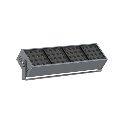
TL-TGD-JA6403 Anti-Glare Single-Row Aimable Flood Light 2...
-
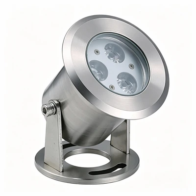
HYD-4075 Mini Surface Mounted Underwater Light 3 W IP68
-

BL-BO16010E-600 Bollard Light 10 W IP65 Die-Cast Aluminum
-

12x25 mm Side Emitting LED Neon Flex GM-H2835Y-120-X-IPX ...
-

BE-WUL0303 In-ground Light 3 W IP67 Aluminium
-

TL-TGD-K1203 Round Flood Light 36 W IP66 Die-Cast Aluminum